

Few lean manufacturing methods increase press uptime, lower per-part costs, and provide an immediate return on investment (ROI) as readily as quick die change (QDC) does. Although the merits of QDC likely are well understood within the stamping field, tailoring a program to a company’s current equipment and operational requirements can be challenging.
Generally, implementing a QDC program is an easy and straightforward process, if it is done by grouping dies and presses in an orderly way. For each group of presses, QDC implementation consists of clamps, die lifting devices, and die removal equipment.
1. Choose Clamp Style
To facilitate quick clamping and unclamping, standardize the clamping method and clamping height for a particular press or group of presses.
Grouping presses by size and die type is the best way to break down your equipment into common components. Look at which dies go into a particular press (or group of presses) and how all the dies are clamped in (see Figure 1). Either:
- Use a single clamp style or size for all the plate and clamp combinations, or
- Standardize dies around one clamping method and, preferably, one clamp plate thickness.
Typically, you will find it beneficial to standardize the clamp plate thickness and clamping method for all dies going into a particular press.
Examining the current plate style provides the information you need to determine which clamp style you need to grip the clamp plate properly.
2. Calculate Clamp Size
Choose the load rating (clamp size) needed to exceed the requirements of the most demanding die.
Clamp size is driven by the maximum die weight that will be run in the press. Typically, you should choose a clamp force for the upper clamps equal to four times the die weight, and then divide that by the number of clamps. Balance the press using an equal number of bottom upper clamps.
Required force per clamp = (Maximum die weight × 4) ÷ No. of clamps
For example, if the ram will be equipped with four clamps and the die weighs 8,000 pounds, you would calculate the per-clamp force as 8,000 × 4 = 32,000 lbs. ÷ 4 = 8,000 lbs. per clamp. Choose the clamp size that exceeds the calculated rating.
Alternatively, for large presses that require many small clamps to distribute the load, determine the quantity of clamps by reversing the formula:
(Maximum die weight × 4) ÷ Clamp force (each) = No. of clamps needed

Figure 1: Clamp types comprise hydraulic-mechanical, hydraulic ledge, and nut.
For proper balance, round up this quantity to the nearest even number of clamps.
For example, if the maximum die weight is 9,000 lbs., and the force per clamp is 8,000 lbs., you would calculate the number of clamps needed by multiplying 9,000 × 4 = 36,000 lbs. ÷ 8,000 lbs. force = 4.5 clamps. Then you would round up to the nearest even number, or 6 ram clamps. Using an equal number of clamps for the bolster totals 12 clamps.
To develop a plant standard, consider all the data from several presses, rather than a single press, when possible.
Warning: Large clamp forces are needed because the press movement causes dynamic loading. These calculations are general recommendations for moderate press speeds and should not be used to determine a particular press requirements without consulting manufacturer recommendations and internal company policy. You must review press speeds and forces and choose the clamp force and quantity to match your application and internal standard operating procedures.
3. Verify Clamp Noninterference
Ensure that the clamps can be moved for die removal and do not interfere with die operation.
Generally, clamps are removed from the slots before a die is inserted or removed. However, if the die size or press arrangement prevents removal, it may be desirable to slide the dies in under the clamps.
In any case, ensure that the ram and bolster plates have the necessary number of slots and locations for the clamps to reach all the dies in the press, as well as clear the dies during installation and removal.
It is recommended that you sketch a diagram indicating basic die locations in the press and clamp locations to check for interference.
4. Determine Die Lifting Requirements
Determine if die lifting is needed to mobilize the die easily during changeover.
Inspect all the dies in the press to ensure their bottoms are flat. Examine the bolster plates, which require full or temporary supports during lifting, for large cutouts or other features that may interfere with a lifting system.
Typically, the bolster has two or more slots under each die running the entire bed length in the direction of die travel. In addition, the die bottoms usually are flat, which allows the dies to ride smoothly on rollers or balls. Small holes and access points are not a problem, if the surface is smooth and large enough to distribute the load over the lifting mechanism.
If the bottom plates are not flat or the bolsters have large cutouts, you will have to consult a supplier for additional, optional equipment.
5. Select Lifting Device Style
Die density drives the selection of lifting device style.
Low-density dies—those that are thin or small relative to their footprint in the press—generally can be lifted with ball roller rails, springloaded ball rails, or ball cartages, which allow the die to be moved in any direction (see Figure 2).
High-density dies usually require several ball-style rails or a pair of heavy-duty roller rails, which move in only one direction, the direction it is inserted, or inline (see Figure 3). If you want the die to move both inline and in the transverse direction, a pair of insertion rails and a pair of transverse rails (see Figure 4) are required.
-

- Figure 2: Ball roller rails (shown), spring-loaded ball rails and ball cartages allow the die to be moved in any direction.
-

- Figure 3: High-density dies usually require a pair of heavy-duty inline roller rails that move in only one direction.
-

- Figure 4: Transverse-travel roller rails allow the dies to move in the opposite direction the die is inserted.
It is important to consider if both directions of movement are needed during the planning process. Generally, it is recommended to plan for both directions of movement to take full advantage of the QDC equipment’s ability to index the die’s exact location and alignment prior to clamping.
6. Calculate Lift Capacity
Select a die lifter with enough power to lift the maximum die weight and move the die in the desired direction.
List out die sizes and weights. Calculate the die load in pounds per foot for each pair of lift rails.
V = Bolster bed length in the direction of slots in feet
W = Die width in the direction of the slots in feet (assuming the slots are in the same direction as die insertion)

Die weight ÷ W = Die load in lbs./ft.
Calculate each die’s density as defined here and determine which has the greatest density. (Note that this is the density along one dimension only and not a volume density calculation.)
Then calculate the lift capacity it needs (available from the manufacturer) in pounds per foot and select the rail type that can lift that densest die. Check the number of slots available under the die, and record it.
Warning: It is very important that you do not select rails’ lift capacity by the overall length. Rails that are as long as the entire bolster allow for the die insertion, but only the length of the rails that is under the die at any given time is actually lifting the die.
Once you have calculated for the heaviest die, confirm that the lifters chosen have the capacity to lift all the dies. Typically, choosing the heaviest die density will ensure correct capacity. However, slot location can be a problem if both large and small dies are run in the same press, because some of the dies might be too small and the rails might not even be under them.
For example, four die lifters are in the bolster to lift a large die, but when small dies are added, only the two middle lifters actually are in a position to do the lifting. You need to verify that the two middle ones can lift all the smaller dies.
Perform this calculation for all dies to verify that each die can be lifted:
Die weight < [W × (Lifting density) × (No. of rails under the specific die)]
Once you have determined which die lifter rail styles and capacities are needed, you can determine the needed overall rail length (typically V or most of it) and slot configuration (3⁄4-inch slots, 1-in. slots, T slot, or rectangular).
7. Choose Die Removal Method
Getting the operating die out and the new die in begins by choosing a die removal method, based on space needs and press operations.
For all die sizes, there are three basic options:
- Mobile platform, such as a forklift
- Permanently mounted die table
- Removable-style bolster extension
Mobile Platform. This is a mobile device that takes the die to the press; provides some type of alignment to it; and has a means of moving the die into the press directly—akin to a very precise forklift with an insertion device. It provides some interesting options, but the control and accuracy limitations of bulk moving equipment typically available may seem contrary to smooth and accurate die placement. For full plant automation installations, such as rail car carts, a mobile platform can provide advantages.
Permanently Mounted Die Table. This is basically a heavy-duty table with rollers attached to the press. It allows die staging and eliminates the need to remove dies from the area, consistent with lean manufacturing principles. However, die tables can interfere with press access and press operations and are a fixed investment.
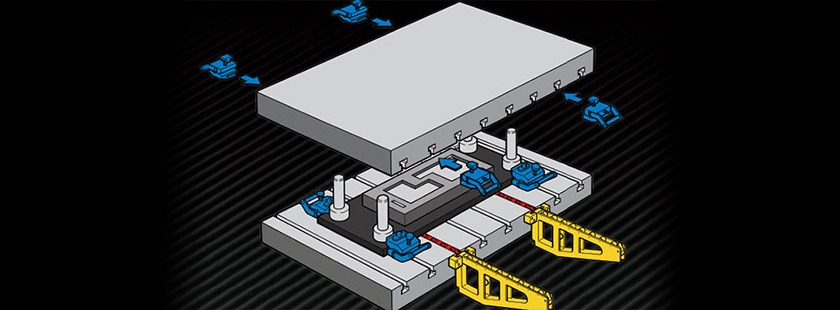
Bolster Extension. These are equipped with rollers that are level with the press’s die lifters and are attached to the press during die movement. Once the die is moved onto the bolster extensions, it is easily accessible from the bottom for removal (see Figure 5). Bolster extensions can be removed or pushed aside, allowing press access. Some styles can be moved from press to press. Bolster extension styles are:
- Small liftoff
- Large rolling liftoff
- Swing-away

Figure 5: Bolster extensions attach to the press to provide controlled die removal and insertion. Shown is a large-die rolling liftoff bolster extension.
For proper sizing, determine which die is the most demanding, as done with the die lifters, and choose extensions that exceed those requirements. Calculate the bolster extension densities compared to the actual load per foot and select the correct bolster extension.
Review all dies for a particular group of presses and consider using only a few pairs of lifters to serve a few (five or six) presses when common die densities make this practical.
8. Select Support Equipment and Installation Method
Consider the controlling/activating equipment—pumps, controls, hoses, manifolds, and mounting devices for the clamps, lifters, and extensions—as well as room for mounting them.
Generally, you’ll need to pay the most attention to selection of manual valves to operate the clamps—either full hydraulic or hydraulic with mechanical locks—and permanently mounted pumps.
Traditionally, fixed hydraulic equipment is attached to presses to facilitate QDC installations. More recently electronic valve controllers tied into the press control or at the press control via keyed switches are used instead.
By recording all the component types on a press-by-press basis, you will notice commonalities and find it easier to standardize some components, which may result in cost reductions and even great ROI on QDC implementations.