Hydraulic Die Lifters/Rollers

Hydraulic Die Lifters

Use Hydraulic Die Lifters for effort free lifting of medium and heavy duty dies.

Use Hydraulic Die Lifters for effort free lifting of medium and heavy duty dies.

When to Use Hydraulic Die Lifters:

Use hydraulic die lifters when die weights are typically standard for medium to large presses. Dies with a small footprint relative to the die weight will typically require Hydraulic Die Lifters.

In addition to a large lifting force, hydraulic actuation allows for easy and controlled movement of the die only when desired, in contrast to spring loaded lifters, typically used in light die applications.

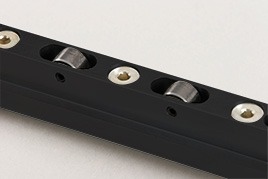
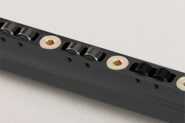
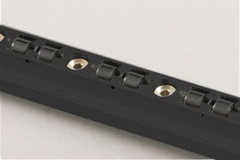
Inline rollers provide for movement along the rail and transverse rollers for movement 90 degrees to the slot direction. Ball roller rails allow for movement in any direction but are generally more limiting in overall die weights.
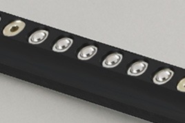
How they are used:

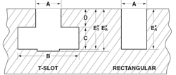
Hydraulic Die Lifter Rails are secured in the slots via the included mounting bracket. Stand offs ensure the rails are captured in the slots, yet move freely up and down prior to die insertion.

The rails are activated using a PFA Hydraulic Control Unit, placing them in the “lifted” position. The die is then inserted by “rolling” into the press and lowered by rotating the control valve to the “lower” position (venting pressure). After insertion, the die may be indexed into position using an additional pair of transverse rollers lifting the die, alternating use of the transverse lifters and inline lifters, using a single pair of ball roller rails, or by other means.

Applications/Sizing

Hydraulic Die Lifter Rails are sized by determining the amount of load per linear foot of depth in the direction of movement, selecting the rail combinations (quanties and types) to meet this requirement, and then crafting the final part number so the rail will fit and function to the actual press T-slot or Rectangular slot dimenions. Note that it is often recommended to use rectangular rails in both rectangular and T-slots as they work in both and eliminate the chance of scrap and debris falling into the slot on the T portion and limiting travel of the die lifter.

The below procedure steps you through the process and has references to the different die lifters on the Die Lifter Models page and to the Sizing page depending on the type of Rail shape desired.  The use of rectangular rails for all slots is recommended.

How to Determine Available Die Lifter Rail Options

1. List out die sizes and weights. Calculate die load per foot, per pair of lift rails. (W=width in feet)
lifter-rail-dimension-1
Die 1 Weight ________ ÷ W = ________ lbs./ft./pair
Die 2 Weight ________ ÷ W = ________ lbs./ft./pair
Die 3 Weight ________ ÷ W = ________ lbs./ft./pair

Determine heaviest die per foot.
Heaviest die density lb./ft./pair = __________________

2. Measure T-Slot or Rectangular channel throat.
If A = .800 to 1.000, use Narrow Rails
If A = 1.000 to 1.25, use Wide Rails
If A = 1.25, contact PFA

3. For the heaviest die, check the number of available slots under the die: Number of available slots = _______________ (See Chart Below)

4. Take the die density from Part 1 and find the closest larger lbs./ft./pair from the chart below. Then move across the top to find your desired die lifter style keeping in mind the Narrow or Wide from Part 2 and the number of available slots from Part 3.

5. Record the rail model number and number of needed rails from the chart:
Model ___________________ Quantity _________

6. Select the Model you desire from the chart below.

7. For the selected model, confirm that the number of rails always supports the dies as follows:
[W ft.] x [Chart lbs./ft./pair] x [No. of Rails] / 2 = [Lift Capacity] >. [Weight lbs.]

Die 1 ______ x ______ x ______ ÷ 2 = ______ > ______
Die 2 ______ x ______ x ______ ÷ 2 = ______ > ______

Ensure lift capacity is greater than die weight.

lifter-rail-dimension-28. Use the Model Number and Bolster Length (V) to determine the rail length desired (see the chart on the Die Lifter Models tab). Lifter will be flush with the loading side and should be near the back side but less than length (V). (Continue with Step 9)

9. With the model and length determined, the profile and final shape of the rail must be calculated. The sizing Rectangular Rails and “T” Rails tabs provide simple calculations to obtain the final information for the part number.


Note: Rail sizing is done for a nominal lift height of the die of approximately .060” – .080” above the bolster surface. If other heights above the surface are desired, contact PFA for easy sizing to those requirements.

Narrow Slot  Wide Slot 
Die Density (lbs./ft./pair) Ball Rollers
317N/318N
(1,800 lbs./ft./pr.)
Cylinder Rollers
315N/316N
(1,800 lbs./ft./pr.)
Ball Rollers
317W/318W
(2,150 lbs./ft./pr.)
Cylinder Rollers
315W/316W/322W
(4,000 lbs./ft./pr.)
Heavy Duty Cylinder Rollers
327W/328W
(9,000 lbs./ft./pr.)
1,800 2 Rails 2 Rails
2,150 3 Rails 2 Rails 2 Rails 2 Rails
2,700 3 Rails 2 Rails 3 Rails 2 Rails
3,225 4 Rails 2 Rails 3 Rails 2 Rails
3,600 4 Rails 2 Rails 4 Rails 2 Rails
4,000 5 Rails 2 Rails 4 Rails 2 Rails
4,300 5 Rails 3 Rails 4 Rails 3 Rails 2 Rails
4,500 5 Rails 3 Rails 5 Rails 3 Rails 2 Rails
5,500 6 Rails 3 Rails 5 Rails 3 Rails 2 Rails
6,000 ** ** ** ** **

**For large die densities, call PFA.

Cylindrical & Ball Rollers

Model No. Slot Rectangular
or T-Slot
Height
Low Profile
High Profile
Length Max Load per foot
(lbs./ ft./ pr.)
Max Load Capacity
(lbs./pr.)
Rollers/ Pistons
(per rail)

Cylindrical Rollers

315N 3/4” (.800)
Narrow
Rectangular 1.495 (LP)
1.805 (HP)
9”
11”
14”
21”
24”
30”
33”
36”
40”
42”
45”
48”
54”
60”
66”
72”
84”
87”
90”
4,000 3,000
4,000
4,000
7,000
8,000
10,000
11,000
12,000
13,000
14,000
15,000
16,000
18,000
20,000
22,000
24,000
28,000
29,000
30,000
04/03
05/04
05/04
08/07
09/08
11/10
12/11
13/12
14/14
15/14
15/15
18/16
20/18
22/20
24/22
26/24
28/28
29/29
30/30
rail-chart-image-1
316N T-Slot
315W 1” (.995)
Wide
Rectangular
316W T-Slot
327W 1” (.995)
Wide
Rectangular 1.495 (LP)
1.805 (HP)
24”
30”
36”
42”
48”
54”
60”
66”
72”
78”
84”
96”
108”
120”
9,000 18,000
22,000
27,000
32,000
36,000
40,000
45,000
49,000
54,000
58,000
63,000
72,000
81,000
93,000
16/08
20/10
24/12
28/14
30/16
34/18
38/20
42/22
46/24
50/26
54/28
60/32
68/36
72/40
rail-chart-image-2
328W T-Slot
322W 1” (.995)
Wide
T-Slot 1.495 (LP)
1.805 (HP)
24”
30”
36”
42”
48”
54”
60”
66”
72”
4,000 8,000
10,000
12,000
14,000
16,000
18,000
20,000
22,000
24,000
14/08
18/10
22/12
26/14
30/16
34/18
38/20
42/22
46/24
rail-chart-image-3

Ball Rollers

317N 3/4” (.800)
Narrow
Rectangular 1.485 (LP)
1.720 (HP)
9”
10”
12”
19”
22”
24”
26”
29”
31”
33”
36”
39”
41”
44”
48”
50”
53”
58”
60”
62”
64”
66”
69”
72”
78”
1,800 1,400
1,500
1,800
2,800
3,300
3,600
3,900
4,300
4,600
4,900
5,400
5,800
6,100
6,600
7,200
7,500
8,200
8,600
8,900
9,200
9,500
9,800
10,300
10,800
11,600
07/02
08/02
10/02
16/03
18/04
20/04
22/04
24/05
26/05
28/05
30/06
32/07
34/07
36/08
40/08
42/08
44/09
48/10
50/10
52/10
54/10
56/10
58/11
60/12
64/14
rail-chart-image-4
318N T-Slot
317W 1” (.995)
Wide
Rectangular 1.485 (LP)
1.720 (HP)
14”
19”
24”
29”
34”
39”
44”
48”
53”
58”
63”
68”
73”
78”
83”
88”
92”
2,150 2,500
3,400
4,300
5,200
6,100
7,000
7,900
8,600
9,500
10,400
11,300
12,200
13,100
14,000
14,900
15,800
16,500
10/03
14/04
18/05
22/06
26/07
30/08
34/09
36/10
40/11
44/12
48/13
52/14
56/15
60/16
64/17
68/18
70/19
318W T-Slot

*Typical lengths – longer rails are available. Contact PFA for details.

Rectangular Rails

How to Size a Rectangular Rail:

Recommended for all slots.
*Nominal .060” to .080” lift above surface of bolster.

  1. Measure Slot Depth (ER) to center bottom:
    ER = __________
  2. Calculate amount of lift needed by piston to raise die desired amount (0.080*) for the chosen rail
    ER + .080* – “H” (LP) = _______ Calculated Piston Stroke
  3. Can piston stroke that much?
    1. If calculated piston stroke is less than .36”, use LP in part number and enter the calculated stroke.  STOP.
    2. If piston stroke is larger than .36”, then try HP calculation:
      ER + .080* – “H” (HP) = _______ Piston Stroke
      If less than .36”, use HP in part number and the calculated stroke
  4. Verify lowered and raised positions fit slot for selected rail.
    1. Is “H” less than (ER)?  If yes, ok.  If no, call PFA
    2. Is (“H” – .080* + .36”) more than (ER)?  If yes, ok.  If no, call PFA
Quick Die Change QDC Lifter Rail How to Size a Die lifter rail in a rectangular slot
T-Slot and Rectangular Drawing

Identify Your Part Number

Example:  6,000 lb. die.  Use 8,000 clamps such as Model 825L, clamp plate thickness (CLH) is 1.0” and has 3/4 T-Slot.

Quick Die Change QDC Air Lifter Rail Part Number specification

** All flange and stroke dimensions are less than 1.000”, thus the decimal is omitted and fraction decimal entered.  For example, a .310” stroke is XXX=310.

*** Standard widths are shown as .800 and .995 for standard rails.  Use 0800 or 0995 for these units or other as desired.  For example, a 1.020 width is YYYY=1020.

For free sizing assistance and application support, please email or fax application dimensions and information to PFA.

"T" Rails

How to Size a “T” Rail:

Only for T-Slots
*Nominal .060” to .080” lift above surface of bolster.

  1. Measure Neck Height (D) and Full Width Depth (ET):
    D = __________
    ET = __________
  2. Calculate amount of Flange Height for desired lift (.080*)
    H (LP) – .080* – D = _______ Anticipated Flange Height
  3. Is anticipated flange height adequate?
    If flange is more than .25”, then ok.
    If not, use calculation below for HP rail.
    H (HP) – .080* – D = _______ Anticipated Flange Height
    If more than .25”, ok.
  4. Verify lowered and raised positions fit slot for selected rail.
    1. Is “H” less than (ET)?  If yes, ok.  If no, call PFA
    2. Is (“H” – .080* + .36”) more than (ET)?  If yes, ok.  If no, call PFA
Quick Die Change QDC Lifter Rail How to Size a Die lifter rail in a T slot
T-Slot and Rectangular Drawing

Identify Your Part Number

Example:  6,000 lb. die.  Use 8,000 clamps such as Model 825L, clamp plate thickness (CLH) is 1.0” and has 3/4 T-Slot.

Quick Die Change QDC Air Lifter Rail Part Number specification

** All flange and stroke dimensions are less than 1.000”, thus the decimal is omitted and fraction decimal entered.  For example, a .310” stroke is XXX=310.

*** Standard widths are shown as .800 and .995 for standard rails.  Use 0800 or 0995 for these units or other as desired.  For example, a 1.020 width is YYYY=1020.

For free sizing assistance and application support, please email or fax application dimensions and information to PFA.

View/Download User Guides

Product Videos

Hydraulic Die Lifter/Roller Bar Oring Seal Replacement Video

Hydraulic Die Lifter Rails, also known as ball bars and roller bars, are secured in the slots via the included mounting bracket. Standoffs on the mounting bolts provide a gap for the bracket and ensure the rails are captured in the slots, yet move freely up and down. The rails are activated using a PFA Hydraulic Control Unit, placing them in the “lifted” position. The die is then inserted by “rolling” into the press and lowered by rotating the control valve on the control unit to the “lower” position (venting pressure).

Using a short DL-316N Hydraulic Die Lifter, the internals of the die lifter are shown as part of the seal replacement procedure. Tips and techniques are demonstrated for easy oring seal replacement.

NEED IT FIXED RIGHT NOW? PFA is REAL SERVICE™

Although most PFA products are built to size, the most critical items are maintained on-the-shelf for rapid availability. Need it to ship in 4 hours or less? We can do it! With real-time technical support, off-the-shelf products, and same day shipping, we can often have you back up and running before you've had your morning coffee. That's REAL SERVICE™.

HAVE A DIFFICULT PROBLEM TO SOLVE? PFA IS THE SOLUTION.

We work with our customers to solve existing problems, and can design custom solutions when needed. With over 25 years of experience reviewing applications and providing custom products, PFA is likely to have the solution to your problem already designed. Call us today and see if we can help!

WONDERING HOW TO INCREASE PRODUCTION? PFA MEANS NO DELAYS.

With a proven off-the-shelf "lean manufacturing" solution from PFA, your application works every time. Using a KOR-LOK® Side-Action System will result in shorter design and manufacturing time and will lead to shorter concept-to-production schedules. KOR-LOK® Preloading Hydraulic Locking Cylinders and Quick Die Change (QDC) clamps are in-stock and ready to ship, so you can start saving time and money with SMED today. From spare parts to complex solutions, PFA is the answer to faster production and more profits.