Hydraulic Control Units

Hydraulic Power Units for Clamps and Rails

Quick Die Change QDC Hydraulic Clamp Control Quick Die Change QDC Hydraulic Clamp Control High Pressure Hydraulic Control Units (HC) are powered with commonly available air pressure and are made in a variety of configurations to optimize all QDC applications. From single valve (zone) carriables to multi-valve units, we’ve got just what you need to get the job done. Here’s a summary.

Hydra-Mechanical (HM) clamps, also known as locking clamps, are hydraulically actuated and then mechanically locked during press operations. They need to be re-pressurized in order for the mechanical locks to be released. HM in the module part number indicates the addition of a hydraulic pressure booster button to make unlocking simple and easy.

Hydraulic Die Lifter Rails provide exceptional lift capacity, but need to be lowered prior to clamping. DL in the part number indicates the addition of a pressure relief valve to help protect the rails in the event dies are clamped before rails are lowered.

Smaller carriable power units are designated as (C) while the larger stationary units can be ordered as Stationary (S) for your own mounting or Mounting Bracket (B), Stationary Pedestal (P) or Rolling Stand (R).

For systems employing hydraulic only (non-locking) clamps it is necessary to, as a minimum, cross connect Ram Clamps with half of them to a separate zone and provide connections to the press control to stop the press on loss of system pressure. Maintaining dedicated controller connections and using the Pressure Switch (PS) option is minimally required/recommended.

MODEL CONFIGURATION OPTIONS
HM Hydra-Mechanical Clamps
DL Die Lifter Dedicated Zone with Overpressure Relief
PS Pressure Switch
S Stationary
C Carriable
R Roll-Around
P Pedestal
B Bracket

Applications/Sizing

Selection of the correct High Pressure Hydraulic Control Unit (HC) for the application should be done in consultation with your PFA representative.  Different options are selected to match installation kit requirements for cross connecting zones, check valves, die lifter reliefs, etc.

Feature summary for typical usage:

Option HM:  Hydra-Mechanical (HM) clamps, also known as locking clamps, are hydraulically actuated and then mechanically locked during press operations. They need to be re-pressurized in order for the mechanical locks to be released. HM in the module part number indicates the addition of a hydraulic pressure booster button to make unlocking simple and easy.

Option DL:  Hydraulic Die Lifter Rails provide exceptional lift capacity, but need to be lowered prior to clamping. DL in the part number indicates the addition of a pressure relief valve to help protect the rails in the event dies are clamped before rails are lowered.

Mounting Options C, R, S, B, and P:  A group of removable (Quick Disconnect) capable systems are designated either Carriable (C) or Roll-Away/Rolling Stand (R).  They combine the feature of portability with an umbilical designed to disconnect air and hydraulics for storage or use on multiple press installations.  Typically used for systems without clamps (Die Lifters Only) or with Locking style (L) Clamps.

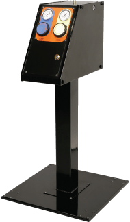
Permanently installed systems are available without a mount  – Stationary (S) with lugs on the bottom for customer designed mounting, Bracket (B) with a small separate shelf, or Pedestal (P) a fixed stand to place the controls at operator height.  Bracket (B) and Pedestal (P) mounts may be ordered separately and added to a Stationary (S) unit.

Option PS:  For systems employing hydraulic only (non-locking) clamps, it is necessary to provide multiple zones to Ram Clamps for redundant sources of pressure.  Typical installation recommendations show half of the upper clamps interspersed or cross-connected on one zone and the remaining clamps on a separate zone to ensure 50% clamping force if one zone experiences an unexpected loss of pressure   The controller is also dedicated to the press and a pressure switch (PS) is added to the controller to provide integration with the press control to stop the press on loss of system pressure. Maintaining dedicated controller connections and using the Pressure Switch (PS) option is minimally required/recommended when using non-locking clamps.

Option PC:  Check valves to each clamp is also an option often requested by customers using non-locking clamps.  Each clamp has an inline pilot operated check valve and allows use of a single zone for all upper clamps.  To provide pilot pressure to open the clamps, an opening pilot circuit (PC) is added to the zone used to operate the upper clamps.


COMMON SPECIFICATIONS
  • Air inlet pressure/150 psi maximum/70 psi minimum
  • Oil temperature range of 50˚-120˚F
  • All hydraulic hose fittings are 37 flare
  • Internal air regulator is pre-set to approximately 70 psi for 5,000 psi hydraulic output to the clamps
  • 0-10,000 psi gauges for each circuit except electrically actuated module
  • Mechanical valves are low friction with metal to metal seals and check valves to isolate each hydraulic circuit. Electronic valves are 24 VDC poppet valves.


Part Combinations and Recommended Module Options
  • Hydraulic Die Lifters Only – Choose a single hydraulic circuit (1 zone) carriable module for convenient use and storage. Great for single or multiple systems. Example: HC-105C-DL
  • Hydra-Mechanical Locking Clamps Only – Choose a two hydraulic circuit (2 zone) carriable or larger roll-around module for greater convenience. HM booster is added for “L” clamp. Typically one hydraulic circuit is connected to the Ram Clamps and the other to the Bolster Clamps.  Example: HC-125C-HM; HC-120S-HM
  • Hydra-Mechanical Locking Clamps and Die Lifter Combination – Choose a three hydraulic circuit (3 zone) module when Hydra-Mechanical Locking Clamps and Die Lifters are used.  Example: HC-130R-HM-DL
  • Hydraulic-Only Clamps* – Choose a three hydraulic circuit (3 zone) module and cross connect top clamps to two separate zones. Since there are no locks, this will be a dedicated always connected controller with pressure sensing switch. Example: HC-130S-PS
  • Hydraulic-Only Clamps* with Die Lifters – Choose a four hydraulic circuit (4 zone) module when cross connecting a dedicated controller for non-locking clamps with Die Lifters.  Example HC-140S-PS-DL

* Clamps may also be secured with check valves to each clamp and operated with pilot control from the power unit Pilot Circuit (PC) option. Call PFA for details.

View/Download User Guides:

Mechanical Valve Power Units

HC-105C-DL

HC-105C-DL
one Zone, One Hydraulic Circuit With DL Option

This carriable unit is most often used to supply power to several machines. It may also be mounted for dedicated operation on a specific machine.

Weight 25 lbs.
Reservoir Capacity 2 1/2 qts.
Dimensions 14"L x 9"W x 11"H

125C-HM Two Zone Two Hydraulic Circuits

HC-125C-HM
Two Zone, Two Hydraulic Circuits with HM Option

This carriable unit is most often used to supply hydraulic power to clamps which are mechanically locked during die operations. Two circuits are provided, one for the Ram Clamps and the other for the Bolster Clamps. It may also be mounted for dedicated operation on a specific machine.

Weight 30 lbs.
Reservoir Capacity 2 1/2 qts.
Dimensions 14"L x 9"W x 11"H

HC-120P-HM TWO ZONE, TWO HYDRAULIC CIRCUITS WITH HM OPTIONS

HC-120P-HM
Two Zone, Two Hydraulic Circuits with HM Options

This unit is most often used for the same applications as the HC-125C-HM but dedicated to a single press or rolled to multiple presses. It is available in either the Stationary (S), Pedestal (P), Bracket (B) or Rolling (R) mounting configurations. Typically used with more complex configurations on custom applications, this unit is the first in the large box modules.

Weight 55 lbs.
Pedestal/Base adds 40 lbs.
Bracket adds 10 lbs.
Roll Around adds 50 lbs.
Reservoir Capacity 4 1/2 qts.
Dimensions Cabinet Only: 21"L x 10"W x 16"H
Pedestal/Base: 29"H
Bracket: 14"L x 10"W x 6"H
Roll Around: 34"H

HC-130R-HM-DL

HC-130R-HM-DL
Three Zone, Three Hydraulic Circuits with HM and DL Options

This unit is most often used to supply hydraulic power to Hydra-Mechanical (HM) “Locking” Clamps and Die Lifters. Three circuits are available, one for the top Ram Clamps, one for the Bolster Clamps and a third which supplies hydraulic pressure to the Die Lifters (DL). The unit is placed on a pedestal attached to a base with easy rolling casters. It can also be placed on a customer supplied mount (HC-130S-HM-DL), a shelf bracket (HC-130B-HM-DL) or a pedestal (HC-130P-HM-DL).

Weight 110 lbs.
Cabinet: 60 lbs.
Pedestal/Base adds 40 lbs.
Bracket adds 10 lbs.
Roll Around adds 50 lbs.
Reservoir Capacity 2 1/2 qts.
Dimensions Cabinet Only: 21"L x 10"W x 16"H
Pedestal/Base: 29"H
Bracket: 14"L x 10"W x 6"H
Roll Around: 34"H

HC-130S-PS

HC-130S-PS
Three Zone, Three Hydraulic Circuits with PS Option

This unit is most often used as a dedicated always connected power unit for supplying hydraulic-only clamps. Two zones each supply hydraulics to half of the Ram Clamps for cross connected capability, with the third zone powering the Bolster Clamps. The PS option ties into the press control for press shut down on loss of system pressure. Available in B (HC-130B-PS) and P (HC-130P-PS) mounting configurations.

Weight 60 lbs.
Pedestal/Base adds 40 lbs.
Bracket adds 10 lbs.
Reservoir Capacity 2 1/2 qts.
Dimensions Cabinet Only: 21"L x 10"W x 16"H
Pedestal/Base: 29"H
Bracket: 14"L x 10"W x 6"H

HC-140S-PS-DL

HC-140S-PS-DL
Four Zone, Four Hydraulic Circuits with PS and DL Options

This unit is used in dedicated always connected applications and operates three zones for clamps exactly like the 130S-PS above, but adds a fourth zone to operate the Die Lifters. Available in B (HC-140B-PS-DL) and P (HC-140P-PS-DL) mounting configurations.

Weight 65 lbs.
Pedestal/Base adds 40 lbs.
Bracket adds 10 lbs.
Reservoir Capacity 2 1/2 qts.
Dimensions Cabinet Only: 21"L x 10"W x 16"H
Pedestal/Base: 29"H
Bracket: 14"L x 10"W x 6"H

Electronic Valve Power Units

Electronic-Valve--Power-Units
Electronic valve versions of our historically popular Mechanical Valve Power Units, provide for a new approach to QDC control. Removing the control interface and shifting that to a remote location allows customers to create or use any control method they choose to operate, lock out, and/or key control the system, and provides the freedom to locate the box itself in a hidden or out of the way location.

Valves to the clamps are normally open which results in constant system pressure to the clamps regardless of power availability. DL circuits have normally closed valves which must be activated to provide pressure to the Die Lifters.

HC-173S-PS
Three Zone Electronic Valves, Three Hydraulic Circuits

This unit is used as a dedicated always connected power unit for supplying hydraulic-only clamps. Two zones each supply hydraulics to half of the Ram Clamps for cross connected capability with the third zone powering the Bolster Clamps. The PS option ties into the press control for press shut down on loss of system pressure. Available in B (HC-173B-PS) and P (HC-173P-PS) mounting configurations.

Weight 60 lbs.
Pedestal/Base adds 40 lbs.
Bracket adds 10 lbs.
Reservoir Capacity 4 1/2 qts.
Dimensions Cabinet Only: 21"L x 10"W x 16"H
Pedestal/Base: 29"H
Bracket: 14"L x 10"W x 6"H
HC-174-PS-DL
Four Zone Electronic Valves Four Hydraulic Circuits

This unit is used in dedicated always connected applications and operates three zones for clamps exactly like the HC-173S-PS above, but adds a fourth zone to operate the Die Lifters. Available in B (HC-174B-PS-DL) and P (HC-174P-PS-DL) mounting configurations.

Weight 65 lbs.
Pedestal/Base adds 40 lbs.
Bracket adds 10 lbs.
Reservoir Capacity 4 1/2 qts.
Dimensions Cabinet Only: 21"L x 10"W x 16"H
Pedestal/Base: 29"H
Bracket: 14"L x 10"W x 6"H
NEED IT FIXED RIGHT NOW? PFA is REAL SERVICE™

Although most PFA products are built to size, the most critical items are maintained on-the-shelf for rapid availability. Need it to ship in 4 hours or less? We can do it! With real-time technical support, off-the-shelf products, and same day shipping, we can often have you back up and running before you've had your morning coffee. That's REAL SERVICE™.

HAVE A DIFFICULT PROBLEM TO SOLVE? PFA IS THE SOLUTION.

We work with our customers to solve existing problems, and can design custom solutions when needed. With over 25 years of experience reviewing applications and providing custom products, PFA is likely to have the solution to your problem already designed. Call us today and see if we can help!

WONDERING HOW TO INCREASE PRODUCTION? PFA MEANS NO DELAYS.

With a proven off-the-shelf "lean manufacturing" solution from PFA, your application works every time. Using a KOR-LOK® Side-Action System will result in shorter design and manufacturing time and will lead to shorter concept-to-production schedules. KOR-LOK® Preloading Hydraulic Locking Cylinders and Quick Die Change (QDC) clamps are in-stock and ready to ship, so you can start saving time and money with SMED today. From spare parts to complex solutions, PFA is the answer to faster production and more profits.