

Please CLICK HERE to go to the KOR-LOK Section for LOCKING CYLINDERS and CORE PULL Cylinders for Injection Molding and Die Casting. For the needs of high pressure injection applications, Preload capability is needed – you will need a KOR-LOK. If you are new to PFA’s products, please review the KOR-LOK product Section and/or contact PFA for our free application review and further assistance. Your success is important to us! Please call.
Self-Locking and Braking Cylinders

ATTENTION MOLD & DIE BUILDERS
Why Self-Locking & Braking Cylinders?
Self-Locking Cylinders and Brake Cylinders allow designers to defeat common barriers associated with hydraulic and pneumatic systems.
Locking Cylinders: Repeatable precise positioning along with high force holding capability is now attainable with PFA Self-Locking Cylinders. The metal-on-metal positive lock ensures “hard contact” repeatability and maintains position independent of system pressure. Because the locking mechanism physically blocks rod movement, common “spongy” air and hydraulic problems are eliminated. Once in the locked position, system pressure may be lost or removed without affecting position or load capacity.
Braking Cylinders: Holding the rod in position when air pressure is lost is the typical use of PFA’s Braking Cylinders. The internal rod brake allows holding in any position.
Modular Support
PFA’s modular systems replace custom and complex systems, allowing for drop-in support. That means that during production runs, when your customers need to do a quick replacement, they can do it.
Some Examples
Lift and load devices, safety mechanisms, and non-drift applications are just three generic examples of possible uses. Specific examples include: foam molding, intermittent use lifting, movable platforms, staking, automated assembly, tooling fixtures, stamping, packaging and many more.
Simpler is Better!
Often by eliminating the need for hydraulics, our pneumatic Self-Locking Cylinders and Braking Cylinders do the job better, faster, and at a lower cost, saving money in design, construction, and lifetime operation. For amazing hydraulic versions with 10x the holding force of standard hydraulic cylinders, try our HYS series.
Discover the Benefits of Control, Protection, Strength and Easy Operation with PFA Self-Locking Cylinders!
- Mechanical Lock Protection. True “rod interrupt” lock ensures full load capacity is maintained, even if system pressure is lost! (HYS/PVS)
- Positive Locking Sensor Control. Senses actual locking action engaging to ensure positive machine control.
- Smooth & Easy Operation. Complementary angles allow for ease of lock engagement and disengagement even under load!
- Strong Compact Design. Integral locking mechanism allows for ease of installation and can hold the force of a cylinder 10 to 15 times larger!
- Standard Porting Flexibility. When cylinder reaches end of stroke the spring bias causes the lock to engage. Retract pressure (LOE) or extend pressure (LOR) is ported internally to unlock the unit, making a 2-port system. (HYS/PVS)
- Adjustable End of Stroke Cushioning. Metered exhaust allows for adjustable cushions at either end of stroke. (HYS/PVS/KPS)
Comparison to Standard Cylinders
| PFA SELF-LOCKING CYLINDERS | vs. | OTHER STANDARD CYLINDERS |
|---|---|---|
| YES! | Move loads based on applied pressure? | YES! |
| YES! | Maintain position/force with pressure drops? | Can’t Do It! |
| YES! | Keep position/force with total loss of pressure? | Can’t Do It! |
| YES! | Hold loads up to 15 times the piston force? | Can’t Do It! |
| YES! | Perform intermittent operation with zero drift? | Can’t Do It! |
HYS/PVS – Hydraulic/Pneumatic Self-Locking Cylinders
Lock-on-Extend (LOE) Style
Application – The Lock-on-Extend (LOE) Self-Locking Cylinder locks the rod in position when the rod is fully extended. Load force is applied to the rod in a direction such that it is pushing on the rod (compression). Lock prevents retraction.
Operation – The Lock-on-Extend (LOE) Self-Locking Cylinder employs a tri-sectional locking ring (three segments) and an annular groove to maintain a metal-on-metal mechanical lock regardless of system pressure. As the cylinder reaches end-of-stroke (extend), the tri-sectional ring is forced into the annular groove in the rod by the locking slide. The locking slide is held in place by the bias springs and will maintain lock-up until pressure is applied to the retract port. The retract port supplies pressure to move the locking slide off the three locking segments and to retract the rod at the same time.
Lock-on-Retract (LOR) Style
Application – The Lock-on-Retract (LOR) Self-Locking Cylinder locks the rod in position when the rod is fully retracted. Load force is applied to the rod in a direction such that it is pulling on the rod (tension). Lock prevents extension.
Operation – The Lock-on-Retract (LOR) Self-Locking Cylinder employs a tri-sectional locking ring (three segments) and an annular groove to maintain a metal-on-metal mechanical lock regardless of system pressure. As the cylinder reaches end-of-stroke (retract), the rod engages a keeper slide allowing the tri-sectional ring is forced into the annular groove by the locking slide. The locking slide is held in place by the bias springs and will maintain lock-up until pressure is applied to the extend port. The extend port supplies pressure to move the locking slide off the three locking segments and to extend the rod at the same time.
KPS Internal Braking Cylinder
Application – The KPS Internal Braking Cylinder is designed for long life when properly utilized. Ideally, the brake element should be engaged when the piston rod is no longer moving. Braking with the cylinder rod stationary will reduce the wear of the braking element and allow for precise positioning. Brake holds rod in any position.
Operation – PFA’s KPS Internal Braking Cylinder provides the freedom to stop and hold a load anywhere along the stroke, without relying on air pressure to hold position. While the KPS functions like any other double-acting pneumatic cylinder during normal cycling, when air pressure is removed from the brake port the internal spring-loaded brake mechanism will engage. The brake mechanism consists of spring washers, cone, brake piston and mandrel. When air pressure is removed from the brake port, the spring washers force the piston to pull the cone into the brake mandrel. As the cone enters the brake mandrel, the mandrel (similar to a collet) is forced to spread, contacting the inside surface of the piston rod and effectively holding it in place. When pressure is applied to the release side of the brake piston, the spring washers are compressed, relieving tension on the brake mandrel and releasing the piston rod. The KPS cylinder rod is now free to move.
Lock on Extend (LOE) Cylinder Types


PVS (Pneumatic/Air/Light Hydraulic)
PVS Style Self-Locking Cylinders are commonly used for applications using air. Often the PVS model replaces or substitutes for more costly hydraulic systems. The solid metal-on-metal lock allows for high loading without the “squish” associated with standard air cylinders.
HYS (Heavy Hydraulic)
HYS Style Self-Locking Cylinders are commonly used for applications where high moving forces are required. HYS is the perfect choice in applications where holding during loss of pressure is critical. The Heavy Hydraulic style may be operated pneumatically in some applications. Consult PFA for details.
Accommodation of Locking Clearance / Overtravel
Self-Locking Cylinders must fully extend to lock at the end of stroke. In many applications, the lock point is not restricted and the cylinder fully extends and locks. In other applications, a more precise lockup window is desirable and may be obtained with simple stops and shims.
To ensure locking, the cylinders are manufactured with .004” to .013” of overtravel (end play) beyond the seating lock position. When pressure is removed or load applied after a locked condition is achieved, the rod will backup or move until the clearance is taken up. The overtravel clearance may be eliminated by adjusting load position at the rod-to-load interface. Consult a PFA Applications Specialist for details.
How it works
As the cylinder reaches end-of-stroke, the tri-sectional ring (A), is forced into the annular groove (B) in the rod by the locking slide (“C”). The locking slide is held in place by the bias springs and will maintain lock-up until pressure is applied to the retract port. The retract port supplies pressure to move the locking slide off the three locking segments and to retract the rod at the same time.
Dimensional Information

NOTE: Application sketches are offered as suggestions only. Feasibility, testing and usage of the product is the responsibility of the user. The product may be used to increase safety, but should not replace positive stop safety mechanisms. No liability is expressed or intended on the part of PFA, Inc., it’s employees or agents.
Simplified Circuit/Sequence-Vertical movement
To support the vertical load and remove force on the lock prior to unlocking and lowering (with possible multiple speeds).
- Valve “CD” is recommended in vertical applications to prevent uncontrolled dropping or movement of the load due to gravity when unlocked.
- ENSURE LOAD IS GUIDED INDEPENDENTLY from the cylinder rod in vertical applications.
- Energize solenoid (C) to lift/support the load off of the locking mechanism.
- Leave (C) energized while energizing (A) to unlock the locking Mechanism (lock sensor off).
- De-energize (C) to lower load at speed set at (FC1).
- Energize (D) to lower load at higher speed based on parallel (combined) flow thru (FC1) and (FC3).
- Energize (B) to lift the load with speed based on (FC2). At full extend the cylinder will lock (sensor on to verify lock).
Simplified Circuit/Sequence-Horizontal Movement
To allow for more simple horizontal cylinder operation.
- Valve “CD” is not needed in the horizontal application, IF the lock is NOT under load during unlocking. However, if the lock IS under load during unlocking, then follow the Vertical movement method.
- ENSURE LOAD IS SUPPORTED INDEPENDENTLY from the cylinder rod in a horizontal application.
- With no load on the lock, Energize A to unlock and retract at speed set by (FC1).
- Energize (B) to extend the load at speed set at (FC2).
Lock-on-Extend (LOE) Theoretical Performance Data
| Lock-on-Extend Style Bore ø / Rod ø | Lock Holding Force** (Fully Extended) | Moving Force-Extending (LBS) Air/Hydraulic Pressure (psi) | Moving Force-Returning (LBS) Air/Hydraulic Pressure (psi) | ||||||
|---|---|---|---|---|---|---|---|---|---|
| 75 | 1000 | 1500 | 3000 | 75 | 1000 | 1500 | 3000 | ||
| PVS–2.000/0.625 | 2,500 lbs. | 235 | Maximum Pressure 1000 psi | 210 | Maximum Pressure 1000 psi | ||||
| PVS–2.500/1.000 | 11,000 lbs. | 365 | Maximum Pressure 1000 psi | 305 | Maximum Pressure 1000 psi | ||||
| PVS–4.000/1.375 | 17,500 lbs. | 940 | Maximum Pressure 1000 psi | 830 | Maximum Pressure 1000 psi | ||||
| PVS–5.000/1.750 | 45,000 lbs. | 1,470 | Maximum Pressure 750 psi | 1,290 | Maximum Pressure 750 psi | ||||
| PVS–6.000/1.750 | 45,000 lbs. | 2,120 | Maximum Pressure 750 psi | 1,930 | Maximum Pressure 750 psi | ||||
| HYS–2.000/1.000 | 20,000 lbs. | 235 | 3,140 | 4,700 | 9,400 | 170 | 2,350 | 3,500 | 7,050 |
| HYS–2.500/1.375 | 30,000 lbs. | 365 | 4,900 | 7,300 | 14,700 | 250 | 3,420 | 5,100 | 10,250 |
| HYS–4.000/1.750 | 50,000 lbs. | 940 | 12,500 | 18,800 | 37,600 | 760 | 10,150 | 15,200 | 30,400 |
* Heavy Hydraulic Style may be operated pneumatically in some applications. Consult PFA for details.
** Cylinder locking / holding force is a function of rod column strength and depends on overall stroke length and proper load guidance/installation.
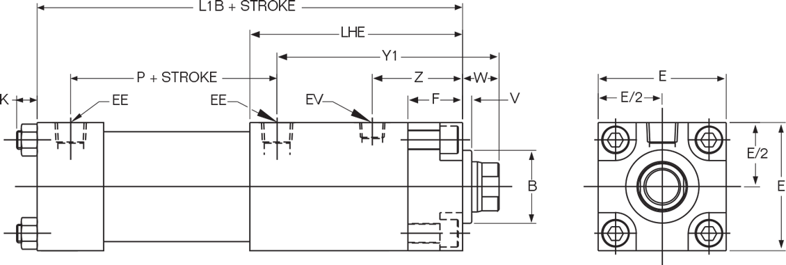
| Style-Bore/Rod ø | B | V | W | E | F | K | EE | EV | P | Y1 | Z | LHE | L1B |
|---|---|---|---|---|---|---|---|---|---|---|---|---|---|
| PVS–2.000/0.625 | 1.124 | 0.25 | 0.63 | 2.50 | 0.75 | 0.25 | 3/8 NPT | 1/4 NPT | 2.87 | 3.95 | 1.281 | 3.75 | 6.81 |
| PVS–2.500/1.000 | 1.499 | 0.25 | 0.75 | 3.00 | 1.00 | 0.46 | 3/8 NPT | 1/4 NPT | 2.86 | 5.52 | 2.076 | 5.25 | 8.25 |
| PVS–4.000/1.375 | 1.998 | 0.25 | 0.88 | 4.50 | 1.50 | 0.51 | 1/2 NPT | 3/8 NPT | 3.25 | 5.51 | 1.792 | 5.14 | 8.62 |
| PVS–5.000/1.750 | 2.375 | 0.25 | 1.00 | 5.50 | 1.75 | 0.75 | 1/2 NPT | #6 SAE | 4.00 | 7.92 | 2.900 | 8.17 | 11.92 |
| PVS–6.000/1.750 | 2.375 | 0.25 | 1.00 | 6.50 | 1.75 | 0.75 | 1/2 NPT | #6 SAE | 4.00 | 7.92 | 2.900 | 8.17 | 11.92 |
| HYS–2.000/1.000 | 1.499 | 0.25 | 0.75 | 3.00 | 1.00 | 0.54 | #8 SAE | #4 SAE | 3.00 | 5.39 | 2.076 | 5.25 | 8.41 |
| HYS–2.500/1.375 | 1.998 | 0.25 | 1.00 | 3.50 | 1.50 | 0.56 | #8 SAE | #6 SAE | 3.64 | 6.08 | 2.470 | 5.82 | 9.63 |
| HYS–4.000/1.750 | 2.375 | 0.25 | 1.00 | 5.00 | 1.75 | 0.63 | #12 SAE | #6 SAE | 4.25 | 7.80 | 2.903 | 8.17 | 11.92 |
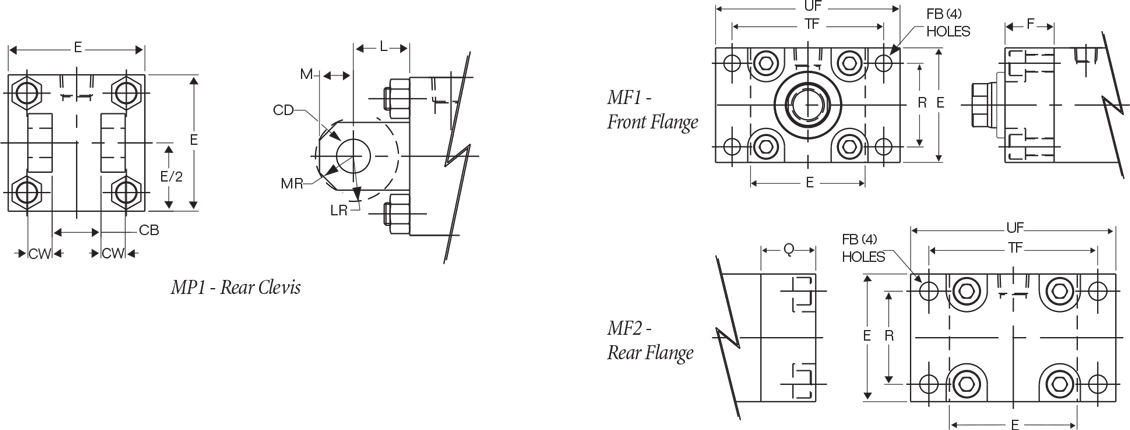
| Series–Bore/Rod ø | CB | CD | CW | L | LR | M | MR | F | FB | R | TF | UF | Q* |
|---|---|---|---|---|---|---|---|---|---|---|---|---|---|
| PVS–2.000/0.625 | 0.75 | 0.50 | 0.50 | 0.75 | 0.63 | 0.50 | 0.63 | 0.750 | 0.406 | 1.844 | 3.375 | 4.125 | 0.750 |
| PVS–2.500/1.000 | 0.75 | 0.50 | 0.50 | 0.75 | 0.63 | 0.50 | 0.63 | 1.000 | 0.438 | 2.192 | 3.875 | 4.625 | 1.000 |
| PVS–4.000/1.375 | 1.25 | 0.75 | 0.63 | 1.25 | 1.00 | 0.75 | 0.85 | 1.500 | 0.438 | 3.320 | 5.440 | 6.250 | 1.500 |
| PVS–5.000/1.750 | 1.25 | 0.75 | 0.63 | 1.25 | 1.00 | 0.75 | 0.94 | 1.750 | 0.560 | 4.100 | 6.625 | 7.630 | 1.750 |
| PVS–6.000/1.750 | CONSULT FACTORY | 1.750 | 0.560 | 4.880 | 7.630 | 8.630 | 1.750 | ||||||
| HYS–2.000/1.000 | 1.25 | 0.75 | 0.63 | 1.25 | 1.00 | 0.75 | 0.88 | 1.000 | 0.500 | 2.050 | 4.125 | 5.125 | 1.000 |
| HYS–2.500/1.375 | 1.25 | 0.75 | 0.63 | 1.25 | 1.00 | 0.75 | 0.88 | 1.500 | 0.500 | 2.550 | 4.625 | 5.625 | 1.500 |
| HYS–4.000/1.750 | 2.00 | 1.38 | 1.00 | 2.13 | 1.75 | 1.38 | 1.63 | 1.750 | 0.656 | 3.818 | 6.375 | 7.625 | 1.750 |
*Q dimension replaces K dimension for MF2–Rear Flange Mount only
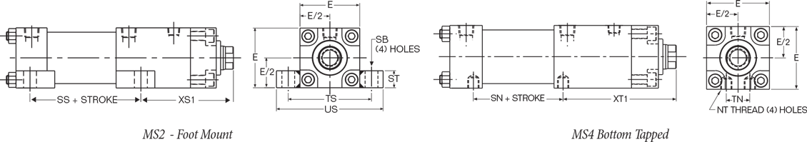
| MS2-Foot Mount | MS4-Bottom Tapped | |||||||||
|---|---|---|---|---|---|---|---|---|---|---|
| Series–Bore/Rod ø | XS1 | SS | SB | ST | TS | US | XT1 | SN | TN | NT |
| PVS–2.000/0.625 | 3.75 | 2.88 | 0.38 | 0.50 | 3.25 | 4.00 | 3.850 | 2.840 | 0.875 | 5/16 – 18 |
| PVS–2.500/1.000 | 5.63 | 3.00 | 0.38 | 0.50 | 3.75 | 4.50 | 5.560 | 2.625 | 1.250 | 3/8 – 16 |
| PVS–4.000/1.375 | 5.75 | 3.25 | 0.50 | 0.75 | 5.50 | 6.50 | CONSULT FACTORY | |||
| PVS–5.000/1.750 | 8.42 | 3.25 | 0.75 | 1.00 | 6.88 | 8.25 | 8.170 | 3.750 | 2.690 | 5/8 – 11 |
| PVS–6.000/1.750 | CONSULT FACTORY | |||||||||
| HYS–2.000/1.000 | 5.50 | 3.25 | 0.50 | 0.75 | 4.00 | 5.00 | 5.430 | 2.875 | 0.938 | 1/2 – 13 |
| HYS–2.500/1.375 | 6.00 | 3.81 | 0.75 | 1.00 | 4.88 | 6.25 | 6.315 | 3.000 | 1.313 | 5/8 – 11 |
| HYS–4.000/1.750 | 8.18 | 3.75 | 1.00 | 1.25 | 6.75 | 8.50 | 8.420 | 3.500 | 2.063 | 1 – 8 |

| Rod End Rod ø | SM or SF KK |
IM CC |
A | D | NA |
|---|---|---|---|---|---|
| 0.625 | 7/16-20 | 1/2-20 | 0.75 | 0.50 | 0.56 |
| 1.000 | 3/4-16 | 7/8-14 | 1.13 | 0.88 | 0.94 |
| 1.375 | 1-14 | 1 1/4-12 | 1.63 | 1.19 | 1.31 |
| 1.750 | 1 1/4-12 | 1 1/2-12 | 2.00 | 1.53 | 1.72 |

Instructions:
Each end of the cylinder has four positions for ports (P), sensors (S), cushion adjustments (C), and mountings (MS2, MS4 use a position).
Catalog drawings show standard ports “on top” in position (1) and standard mounts “on the bottom” in position (3). Mounts MF1, MF2, and MP1 are oriented as shown in the drawings relative to position (1) “on top.”
NOTE: NO ADDITIONAL ORDER CODE IS REQUIRED TO OBTAIN THE STANDARD ORIENTATION.
When an alternate locations are desired for Ports, Cushions, Mounts, or Sensors, use the Figure above to select positions, remembering that each position can have only one option. Add the three character code(s) to the part number for each option. Sensors are all solid state, Normally Open style, available in 20-250 VAC/DC (load only) [-XAC] and 10-65 VDC [PNP]. PNP is recommended for most PLC type applications.
Note: Other mounting options and mating accessories are available. Please contact PFA for details on your specific application.
Identify Your Part Number

Lock on Retract (LOR) Cylinder Types


PVS (Pneumatic/Air/Light Hydraulic)
PVS Style Self-Locking Cylinders are commonly used for applications using air. Often the PVS model replaces or substitutes for more costly hydraulic systems. The solid metal-on-metal lock allows for high loading without the “squish” associated with standard air cylinders.
HYS (Heavy Hydraulic)
HYS Style Self-Locking Cylinders are commonly used for applications where high moving forces are required. HYS is the perfect choice in applications where holding during loss of pressure is critical.
Accommodation of Locking Clearance / Overtravel
Self-Locking Cylinders must fully retract to lock at the end of stroke. In many applications, the lock point is not restricted and the cylinder fully extends and locks. In other applications, a more precise lockup window is desirable and may be obtained with simple stops and shims.
To ensure locking, the cylinders are manufactured with .004” to .013” of overtravel (end play) beyond the seating lock position. When pressure is removed or load applied after a locked condition is achieved, the rod will backup or move until the clearance is taken up. The overtravel clearance may be eliminated by adjusting load position at the rod-to-load interface. Consult a PFA Applications Specialist for details.
How it works
As the cylinder reaches end-of-stroke, the rod engages a keeper slide allowing the tri-sectional ring (D), to be forced into the annular groove (E) by the locking slide (F). The locking slide is held in place by the bias springs and will maintain lock-up until pressure is applied to the extend port. The extend port supplies pressure to move the locking slide off the three locking segments and to extend the rod at the same time.
Dimensional Information

NOTE: Application sketches are offered as suggestions only. Feasibility, testing and usage of the product is the responsibility of the user. The product may be used to increase safety, but should not replace positive stop safety mechanisms. No liability is expressed or intended on the part of PFA, Inc., it’s employees or agents.
Simplified Circuit/Sequence-Vertical movement
To support the vertical load and remove force on the lock prior to unlocking and lowering (with possible multiple speeds).
- Valve “CD” is recommended in vertical applications to prevent uncontrolled dropping or movement of the load due to gravity when unlocked.
- ENSURE LOAD IS GUIDED INDEPENDENTLY from the cylinder rod in vertical applications.
- Energize solenoid (C) to lift/support the load off of the locking mechanism.
- Leave (C) energized while energizing (A) to unlock the locking Mechanism (lock sensor off).
- De-energize (C) to lower load at speed set at (FC1).
- Energize (D) to lower load at higher speed based on parallel (combined) flow thru (FC1) and (FC3).
- Energize (B) to lift the load with speed based on (FC2). At full retract the cylinder will lock (sensor on to verify lock).
Simplified Circuit/Sequence-Horizontal Movement
To allow for more simple horizontal cylinder operation.
- Valve “CD” is not needed in the horizontal application, IF the lock is NOT under load during unlocking. However, if the lock IS under load during unlocking, then follow use the Vertical application method above.
- ENSURE LOAD IS SUPPORTED INDEPENDENTLY from the cylinder rod in a horizontal application.
- With no load on the lock, Energize A to unlock and extend at speed set by (FC1).
- Energize (B) to retract the load at speed set at (FC2).
Lock-on-Retract (LOR) Theoretical Performance Data
| Lock-on-Retract Style Bore ø / Rod ø |
Lock Holding Force** (Fully Retracted) |
Moving Force-Extending (LBS) Air/Hydraulic Pressure (psi) | Moving Force-Returning (LBS) Air/Hydraulic Pressure (psi) | ||||||
|---|---|---|---|---|---|---|---|---|---|
| 75 | 1000 | 1500 | 3000 | 75 | 1000 | 1500 | 3000 | ||
| PVS–2.500 / 1.000 | 10,000 lbs. | 365 | Maximum Pressure 1000 psi | 305 | Maximum Pressure 1000 psi | ||||
| PVS–4.000 / 1.375 | 15,000 lbs. | 940 | Maximum Pressure 1000 psi | 830 | Maximum Pressure 1000 psi | ||||
| PVS–5.000 / 1.750 | 42,000 lbs. | 1,470 | Maximum Pressure 750 psi | 1,290 | Maximum Pressure 750 psi | ||||
| HYS–2.000 / 1.000 | 9,500 lbs. | 235 | 3,140 | 4,700 | 9,400 | 170 | 2,350 | 3,500 | 7,050 |
| HYS–2.500 / 1.375 | 14,000 lbs. | 365 | 4,900 | 7,300 | 14,700 | 250 | 3,420 | 5,100 | 10,250 |
| HYS–4.000 / 1.750 | 25,000 lbs. | 940 | 12,500 | 18,800 | 37,600 | 760 | 10,150 | 15,200 | 30,400 |
* Heavy Hydraulic Style may be operated pneumatically in some applications. Consult PFA for details.
** Cylinder locking / holding force is a function of rod column strength and depends on overall stroke length and proper load guidance/installation.

| Style-Bore / Rod ø | B | V | W | E | F | K | EE | EV | P | X | Y | LHR | L2B |
|---|---|---|---|---|---|---|---|---|---|---|---|---|---|
| PVS–2.500 / 1.000 | 1.499 | 0.25 | 0.75 | 3.00 | 1.00 | 0.31 | 3/8 NPT | 1/4 NPT | 2.74 | 2.58 | 2.62 | 5.75 | 9.87 |
| PVS–4.000 / 1.375 | 1.998 | 0.25 | 1.00 | 4.50 | 1.50 | 0.06 | 1/2 NPT | 3/8 NPT | 3.25 | 2.40 | 3.44 | 5.75 | 10.94 |
| PVS–5.000 / 1.750 | 2.375 | 0.25 | 1.00 | 5.50 | 1.75 | 0.63 | 1/2 NPT | #6 SAE | 4.00 | 3.40 | 4.25 | 8.67 | 14.67 |
| HYS–2.000 / 1.000 | 1.499 | 0.25 | 0.75 | 3.00 | 1.00 | 0.50 | #8 SAE | #4 SAE | 2.87 | 2.83 | 2.61 | 6.00 | 10.13 |
| HYS–2.500 / 1.375 | 1.998 | 0.25 | 1.00 | 3.50 | 1.50 | 0.50 | #8 SAE | #6 SAE | 3.43 | 2.72 | 3.63 | 6.07 | 11.38 |
| HYS–4.000 / 1.750 | 2.375 | 0.25 | 1.00 | 5.00 | 1.75 | 0.63 | #12 SAE | #6 SAE | 4.25 | 3.40 | 4.12 | 8.67 | 14.67 |

| Series–Bore/Rod ø | CB | CD | CW | L | LR | M | MR | F | FB | R | TF | UF | Q* |
|---|---|---|---|---|---|---|---|---|---|---|---|---|---|
| PVS–2.500 / 1.000 | 0.75 | 0.50 | 0.50 | 0.75 | 0.63 | 0.50 | 0.63 | 1.000 | 0.438 | 2.192 | 3.875 | 4.625 | 1.000 |
| PVS–4.000 / 1.375 | 1.25 | 0.75 | 0.63 | 1.25 | 1.00 | 0.75 | 0.85 | 1.500 | 0.438 | 3.320 | 5.440 | 6.250 | 1.500 |
| PVS–5.000 / 1.750 | 1.25 | 0.75 | 0.63 | 1.25 | 1.00 | 0.75 | 0.94 | 1.750 | 0.560 | 4.100 | 6.625 | 7.630 | 1.750 |
| HYS–2.000 / 1.000 | 1.25 | 0.75 | 0.63 | 1.25 | 1.00 | 0.75 | 0.88 | 1.000 | 0.500 | 2.050 | 4.125 | 5.125 | 1.000 |
| HYS–2.500 / 1.375 | 1.25 | 0.75 | 0.63 | 1.25 | 1.00 | 0.75 | 0.88 | 1.500 | 0.500 | 2.550 | 4.625 | 5.625 | 1.500 |
| HYS–4.000 / 1.750 | 2.00 | 1.38 | 1.00 | 2.13 | 1.75 | 1.38 | 1.63 | 1.750 | 0.656 | 3.818 | 6.375 | 7.625 | 1.750 |
*Q dimension replaces K dimension for MF2–Rear Flange Mount only

| MS2-Foot Mount | MS4-Bottom Tapped | |||||||||
|---|---|---|---|---|---|---|---|---|---|---|
| Series–Bore/Rod ø | XS | DSS | SB | ST | TS | US | XT | SN | TN | NT |
| PVS–2.500 / 1.000 | 2.12 | 3.13 | 0.38 | 0.50 | 3.75 | 4.50 | 2.688 | 2.625 | 1.250 | 3/8 – 16 |
| PVS–4.000 / 1.375 | 3.00 | 3.44 | 0.50 | 0.75 | 5.50 | 6.50 | CONSULT FACTORY | |||
| PVS–5.000 / 1.750 | 4.25 | 3.50 | 0.75 | 1.00 | 6.88 | 8.25 | 4.130 | 3.880 | 2.690 | 5/8 – 11 |
| HYS–2.000 / 1.000 | 2.11 | 3.25 | 0.50 | 0.75 | 4.00 | 5.00 | 2.560 | 2.875 | 0.938 | 1/2 – 13 |
| HYS–2.500 / 1.375 | 3.50 | 3.63 | 0.75 | 1.00 | 4.88 | 6.25 | 3.813 | 3.000 | 1.313 | 5/8 – 11 |
| HYS–4.000 / 1.750 | 4.00 | 4.00 | 1.00 | 1.25 | 6.75 | 8.50 | 4.250 | 3.500 | 2.063 | 1 – 8 |

| Rod End Rod ø | SM or SF KK |
IM CC |
A | D | NA |
|---|---|---|---|---|---|
| 0.625 | 7/16-20 | 1/2-20 | 0.75 | 0.50 | 0.56 |
| 1.000 | 3/4-16 | 7/8-14 | 1.13 | 0.88 | 0.94 |
| 1.375 | 1-14 | 1 1/4-12 | 1.63 | 1.19 | 1.31 |
| 1.750 | 1 1/4-12 | 1 1/2-12 | 2.00 | 1.53 | 1.72 |
Instructions:
Each end of the cylinder has four positions for ports (P), sensors (S), cushion adjustments (C), and mountings (MS2, MS4 use a position).
Catalog drawings show standard ports “on top” in position (1) and standard mounts “on the bottom” in position (3). Mounts MF1, MF2, and MP1 are oriented as shown in the drawings relative to position (1) “on top.”
NOTE: NO ADDITIONAL ORDER CODE IS REQUIRED TO OBTAIN THE STANDARD ORIENTATION.
When an alternate locations are desired for Ports, Cushions, Mounts, or Sensors, use the Figure above to select positions, remembering that each position can have only one option. Add the three character code(s) to the part number for each option. Sensors are all solid state, Normally Open style, available in 20-250 VAC/DC (load only) [-XAC] and 10-65 VDC [PNP]. PNP is recommended for most PLC type applications.
Note: Other mounting options and mating accessories are available. Please contact PFA for details on your specific application.
Identify Your Part Number

Braking Cylinders (KPS)

Advantages
The KPS braking cylinder will automatically engage the brake if air pressure is lost, making it valuable in applications where avoiding potential damage to machinery is a priority.
With the braking action taking place inside the rod, there is no risk of damaging the outside of the rod, which may lead to seal failure in other products.
Since the KPS brake is adjustable, a great degree of control is achievable to facilitate highly complex applications.
How it works
As the cylinder reaches the desired position, air pressure is released from the brake piston (G), allowing the springs (J) to expand and pull the brake cone (K) to engage the brake (L). The brake holds the rod in place until pressure is applied to the brake port and the springs are compressed releasing the brake.
General Specifications
| Piston Diameter | 2.00” – 6.00” |
| Operating Pressure | 250 psi Max. |
| Control Pressure | 75 psi Min. |
| Stroke Speed | 3 ft./sec. Max. |
| Operating Temperature | -40˚F – +250˚F |
| Shell Material | Aluminum, Anodized |
| Rod Material | Steel, Hard Chrome Plated |
| Seals | Buna-N Standard |
| Rod Bushings | Bronze |
| Ports | NPT Standard |
Note: General specifications apply to standard KPS cylinders. Certain aspects of the KPS cylinder may be customized to accommodate individual applications. Please contact PFA for application assistance.
Dimensional Information

NOTE: Application sketches are offered as suggestions only. Feasibility, testing and usage of the product is the responsibility of the user. The product may be used to increase safety, but should not replace positive stop safety mechanisms. No liability is expressed or intended on the part of PFA, Inc., it’s employees or agents.
Simplified Circuit/Sequence-Vertical Movement
To support the vertical load and remove force on the brake prior to unbraking and lowering or raising the load. NOTE: BRAKE is ON when ZERO PRESSURE at Brake Port. Applying pressure disengages brake.
- Very careful control of the pneumatics is needed in vertical applications to prevent uncontrolled dropping or movement of the load due to gravity when brake is disengaged.
- ENSURE LOAD IS GUIDED INDEPENDENTLY from the cylinder rod in vertical applications.
- With solenoid (C) in the normal position the load is supported and the braking mechanism holds position. SUPPLIED PRESSURE SHOULD BE REGULATED AND SET TO EXCEED THE WEIGHT OF THE LOAD SO THE LOAD LIFTS AT ALL TIMES.
- Energize (A) to pressurize the brake ports and disengage the brake (load may lift).
- Maintain (A) energized and Energize(C) or energize (B) to retract the load at the speed set at flow control or energize (B) to power load downward at a higher pressure (preferred).
Simplified Circuit/Sequence-Horizontal Movement
To allow for more simple horizontal cylinder operation.
- Valve (B) would be setup in the same arrangement as (C) so air is constantly supplied to both sides of the piston at pressures determined to balance the piston areas and have nearly no movement.
- ENSURE LOAD IS SUPPORTED INDEPENDENTLY from the cylinder rod in a horizontal application.
- With no load on the brake (balanced), Energize A to disengage the brake.
- Maintain (A) energized and Energize(C) to extend the load at speed set a Flow Control on valve C (meter out), or energize (B) to retract the load at the speed set at Flow Control on valve B.
Braking Cylinders Theoretical Performance Data
| Cylinder Bore Diameter | Extend Force at 90psi | Retract Force at 90psi | Holding Force* at 90psi |
|---|---|---|---|
| 2.00 | 240 | 210 | 290 |
| 2.50 | 400 | 365 | 450 |
| 3.25 | 650 | 560 | 800 |
| 4.00 | 1,000 | 940 | 1,100 |
| 6.00 | 2,400 | 2,300 | 3,200 |
* Holding forces are approximate and based on factory settings using clean, dry air. Customer can vary the holding force by following adjustment procedures provided with the product.

| Bore / Rod ø |
LB | P1 | P | EE | B | C | D | E | G | J | V | NT | SN | TK | TN | WF | XT | ZJ |
|---|---|---|---|---|---|---|---|---|---|---|---|---|---|---|---|---|---|---|
| 2.00 / 0.985 | 8.63 | 7.07 | 2.98 | 3/8 | 1.38 | 0.50 | 0.88 | 2.50 | 1.47 | 5.03 | 0.81 | 5/16-18 | 7.25 | 0.44 | 0.88 | 1.38 | 2.31 | 10.01 |
| 2.50 / 0.985 | 8.75 | 7.26 | 3.02 | 3/8 | 1.38 | 0.50 | 0.88 | 3.00 | 1.47 | 5.15 | 0.81 | 3/8-16 | 7.38 | 0.63 | 1.25 | 1.38 | 2.31 | 10.13 |
| 3.25 / 1.575 | 10.50 | 8.75 | 2.50 | 1/2 | 2.13 | 0.75 | 1.25 | 3.75 | 1.75 | 7.50 | 1.00 | 1/2-13 | 8.88 | 0.75 | 1.50 | 1.94 | 2.94 | 12.44 |
| 4.00 / 1.575 | 10.75 | 9.00 | 2.50 | 1/2 | 2.13 | 0.75 | 1.25 | 4.50 | 1.75 | 7.75 | 0.88 | 1/2-13 | 9.13 | 1.00 | 2.06 | 1.81 | 2.94 | 12.56 |
| 6.00 / 1.575 | 11.53 | 9.30 | 2.90 | 1/2 | 2.38 | 0.75 | 1.25 | 6.50 | 1.98 | 7.91 | 0.88 | 3/4-10 | 9.65 | 1.13 | 3.25 | 1.88 | 3.06 | 13.41 |

| Bore | R | FB | F | TF | UF | E | W |
|---|---|---|---|---|---|---|---|
| 2.00 | 1.84 | 0.34 | 0.38 | 3.38 | 4.13 | 2.50 | 1.00 |
| 2.50 | 2.19 | 0.32 | 0.38 | 3.88 | 4.63 | 3.00 | 1.00 |
| 3.25 | 2.76 | 0.40 | 0.63 | 4.69 | 5.50 | 3.75 | 1.43 |
| 4.00 | 3.32 | 0.38 | 0.63 | 5.44 | 6.25 | 4.50 | 1.43 |
| 6.00 | 4.88 | 0.53 | 0.75 | 7.63 | 8.63 | 6.50 | 1.13 |

| MT1-Front Trunion Mount | MS2-Foot Mount | ||||||||||
|---|---|---|---|---|---|---|---|---|---|---|---|
| Bore | TD | TL | UT | XG | SB | SS | ST | SW | TS | US | XS |
| 2.00 | 1.00 ± .002 | 1.00 | 4.50 | 2.11 | 0.44 | 7.88 | 0.13 | 0.50 | 3.25 | 4.00 | 1.75 |
| 2.50 | 1.00 ± .002 | 1.00 | 5.00 | 2.11 | 0.44 | 8.00 | 0.13 | 0.50 | 3.75 | 4.50 | 1.75 |
| 3.25 | 1.00 ± .002 | 1.00 | 5.75 | 2.88 | 0.54 | 9.50 | 0.19 | 0.69 | 4.75 | 5.75 | 2.44 |
| 4.00 | 1.00 ± .002 | 1.00 | 6.50 | 2.81 | 0.54 | 9.75 | 0.25 | 0.75 | 5.50 | 6.50 | 2.31 |
| 6.00 | 1.38 ± .002 | 1.38 | 9.25 | 2.87 | 0.80 | 10.15 | 0.25 | 0.94 | 7.88 | 9.25 | 2.56 |

| Bore | Rod ø | A | AI | C | CC | KK | KT |
|---|---|---|---|---|---|---|---|
| 2.00 | .985 | 0.75 | 1.13 | 0.50 | 1-14 | 7/16-20 | 7/16-20 |
| 2.50 | .985 | 0.75 | 1.13 | 0.50 | 1-14 | 7/16-20 | 7/16-20 |
| 3.25 | 1.575 | 1.13 | 1.63 | 0.75 | 1 3/8-12 | 3/4-16 | 3/4-16 |
| 4.00 | 1.575 | 1.13 | 1.63 | 0.75 | 1 3/8-12 | 3/4-16 | 3/4-16 |
| 6.00 | 1.575 | 1.63 | 1.63 | 0.75 | 1 3/8-12 | 1-14 | 3/4-16 |
Note: Other mounting options and mating accessories are available. Please contact PFA for details on your specific application.
Identify Your Part Number

Sensors, Lock on Extend (-1)

For Lock-On-Extend cylinders the sensor closest to the rod end, also called the “front or forward sensor” senses the lock itself and can only be activated when the rod is fully extended and the lock is engaged. As the cylinder cannot lock until in the fully extended position, the front sensor acts as both a lock verification sensor and extended verification sensor.
The sensor closest to the opposite end (blind end), also called the “rear or back sensor” senses the piston and can only be activated when the Lock-On-Extend cylinder is in the fully retracted position.
The sensor locations can be in any of four locations around the outside of the cylinder, but cannot be co-located with a cushion adjustment (cushion location), port location, or mount location (if applicable). Positions are noted as front location then rear location, and then quadrant clockwise from the top position 1 when looking down the rod toward the cylinder. For a Lock-On-Extend cylinder with Lock sensor only, specify “S” for “Sensor” then position 1,2,3, or 4 for location on the front, and then 0 for the rear location, where zero stands for none. Typically we recommend to stay with the default recommendations of Ports in position 1, Cushions in position 2, and Sensors in Positon 4. For example P11-C22-S44.
Examples for Lock-On-Extend sensors:
Front Locking Sensor Only: SX0 S10, S20, S30, S40
Rear Position Sensor Only: S0X S01, S02, S03, S04
Both Sensors: S11, S12, S13, S14, S21, S22, …. S44
AC Sensor (-XAC)

Sensors shown are generally typical. Various similar sensors may be installed from several manufacturers with similar functions. Consult PFA for specific sensor dimensions in production at time of order.

Specifications
| Operating Voltage | 20-250 VAC/DC |
| Voltage Drop | < 6 V at 400 mA |
| Output | Normally Open 2-Wire |
| Operating Temperature | -13˚F to +158˚F |
| LED | Green is Power On Red is Output On |
| Pressure | 1500 PSI (max app. 3000 psi) |
| Connector Type | 7/8”-16 Mini Style Male – 3 pin |
| Alternate Wire Colors Depending on Standard |
Pin 1 GRN Pin 2 BLK Pin 3 WHT |
Sensors, Lock on Retract (-2)

For Lock-On-Retract cylinders the sensor on the blind end (farthest from the rod end), also called the “rear or back sensor”, senses the lock itself and can only be activated when the rod is fully retracted and the lock is engaged. As the cylinder cannot lock until in the fully retracted position, the rear sensor acts as both a lock verification sensor and retract verification sensor.
The sensor closest to the rod end, also called the “front or forward sensor” senses the piston and can only be activated when the Lock-On-Retract cylinder is in the fully extended position.
The sensor locations can be in any of four locations around the outside of the cylinder, but cannot be co-located with a cushion adjustment (cushion location), port location, or mount location (if applicable). Positions are noted as front location then rear location, and then quadrant clockwise from the top position 1 when looking down the rod toward the cylinder. For a Lock-On-Retract cylinder with Lock sensor only, specify “S” for “Sensor” then 0 for the front location, where zero stands for none, and then position 1,2,3, or 4 for location on the rear. Typically we recommend to stay with the default recommendations of Ports in position 1, Cushions in position 2, and Sensors in Positon 4. For example P11-C22-S44 (See page 13).
Examples for Lock-On-Retract sensors:
Front Position Sensor Only: SX0 S10, S20, S30, S40
Rear Locking Sensor Only: S0X S01, S02, S03, S04
Both Sensors: S11, S12, S13, S14, S21, S22, …. S44
DC Sensors (-PNP)

Sensors shown are generally typical. Various similar sensors may be installed from several manufacturers with similar functions. Consult PFA for specific sensor dimensions in production at time of order.

Specifications
| Operating Voltage | 10 – 65 V DC |
| Voltage Drop | 2 V at 200 mA |
| Output | Normally Open 3-Wire |
| Operating Temperature | -13˚F to +167˚F |
| LED | Green is Power On Yellow is Output On |
| Pressure | 1500 PSI (max app. 3000 psi) |
| Connector Type | M12x1 Euro/Micro Style Male – 4 pin |
Note: AC sensors may be used for DC Loads such as coils, but are not functional in DC PLC or control circuit applications. DC sensors are generally recommended for PLC applications. PNP style are typically used with NPN available for some legacy applications. Contact PFA for details.
Download 3D Model CAD Files in Any Format
PFA provides FREE APPLICATION REVIEW SUPPORT and parametric 3D CAD models in partnership with CADENAS Part Solutions.
Click the button below to launch the CAD file finder in a new window where you’ll be able to input information and download CAD files.
Please review the below recommendations and instructions.
NEW Users – Forgot Password – Login and Email domain Hints
All “free-mail” domains such as Gmail, Yahoo, Hotmail, etc. are blocked due to SPAM related issues and cannot be used to receive CAD file downloads. Please use a corporate email account when logging into the configurator.
New user registration, updating registration, and password reset may result in the system opening a new browser tab. After completing login or password reset, a new page may load with generic information. Please close the new tab and proceed by clicking “OK” on the original tab behind it. If the page looks unfamiliar or confusing, please reload the page and reenter the product parameters. We are working to improve the new user experience with CADENAS and apologize for any confusion. Please contact PFA for assistance.
FREE Application Review Support
Our Applications Specialists have reviewed thousands of applications. Let our experience work for you! Please contact us early in the design process or email your concept to discuss recommended options. We can open 2D and 3D files in a wide variety of formats. Typically we will not have a problem opening any file format, however, STEP files seem to be the most versatile.
We will provide our recommendations for size and lock holding capacity, and point out any possible limitations of the proposed design affecting proper performance. While the designer is responsible for understanding and selecting the correct product, we are very happy to help optimize that process.
Entering 3D Model Information – Download Instructions:
Parametric 3D Models and 2D CAD Files are available in about 100 native formats, by partnering with CADENAS Part Solutions. In the table below is a menu on the left and image pane for the model on the right. For a better understanding of dimensions, See the Dimensional Information on our website – Lock on Extend (LOE) dimensional information section or Lock on Retract (LOR) dimensional information section. For additional information on selecting CAD file options, help for specific CAD systems, or more details on how to use the configurator, please see instruction below. For additional information on selecting CAD file options, help for specific CAD systems, or more details on how to use the configurator, please see help in the instructions below.
Selecting Product Information – After reviewing the PFA sizing methods and recommendations, select all the options for the Self-Locking cylinder desired and accessories needed:
- Bore Size – Select Piston Diameter/Bore size
- Series – Select PVS (pneumatic) or HYS (hydraulic).
- Lock Position – Lock-On Extend (LOE) or Lock-On Retract (LOR)
- Stroke – Enter Stroke length to .001” (between .1” and 50”)
- Mount – Select Mounting Option
- Rod End – Select SM, IM, or SF
- High Temp Seals Option – For applications where contact or the environment exceeds 200 F add High Temp Seals.
- Select Port Position for front and rear locations – 1 is on top. See Dimensions page for how to determine position.
- Cushion Adjustment Options – Select Cushions for Without (none), Front, Rear, or Both.
- Cushion for front and rear locations – For cushion select location. See Dimensions page for how to determine position.
- Sensor Options – Select Sensors for Without (none), Front, Rear, or Both.
- Stroke Position – Sets the Rod Extended or Retracted when the model is created.
- Sensor Type – Note that sensors look the same whether ACX or PNP. Please remember to specify when ordering.
Preview Tab and Update – Select “Update Preview” in the center of the image area. The model will be created and can be rotated by clicking and holding while moving the mouse as is typical in many CAD systems. The small menu on the upper left and various action buttons on the bottom can be used to gain various impressions of the model and some dimensions. New accessories may be selected and new models generated. Selecting the Dimensions Tab in the image window will bring up 2D layouts. The letters on the drawings reference dimensions shown on the left below the selectable options.
CAD Download Tab – Click on the CAD Download Tab on the upper left of the window and then the Generate CAD button. If you are a returning customer and remember passwords, login to continue or the system may log you in automatically. Click on the Generate CAD button to load the current configuration after login. The system will remember your CAD model file type, but if you are a new user or have not downloaded files recently, it may prompt for details on your CAD system or require accepting new user terms (seen below). Select the “Edit CAD Formats” link on the bottom right next to your email or the small menu box next to the Generate CAD button to change file formats.
New Users/Forgot Password/Free Email Domains – New user registration, updating registration, and password reset may result in the system opening a new browser tab. After completing login or password reset, a new page may load with generic information. Please close the new tab and proceed by clicking “OK” on the original tab behind it. If the page looks unfamiliar or confusing, please reload the page and reenter the product parameters. We are working to improve the new user experience with CADENAS and apologize for any confusion. Please contact PFA for assistance.
Reminder, all “free-mail” domains such as Gmail, Yahoo, Hotmail, etc. are blocked due to SPAM related issues and cannot be used to receive CAD file downloads. Please use a corporate email account when logging into the configurator.
CAD File Download – After selecting the correct file type and selecting Generate CAD, an image of a cylinder and part number file name should appear in the center of the window. Please allow time for the file to generate. Select Information to view the file type information, Download, or Delete to update parameters. (See Help below for additional information on special file types to determine if additional advice, downloads, or support is needed for using the files).
Help – Most files are simple and downloads easy to import, however for those interested in advanced features or for those using CATIA (CATIA Support) and SolidWorks (SolidWorks Support), viewing the help files is recommended to ensure smooth and successful results. Configurator Help reviews items that affect the ability to operate the online viewer and what file types are available. Typically customers have a smooth experience, however, the configurator does require that JAVA (Chrome and Firefox) is installed and enabled and will prompt for the installation of Active X if not installed. Different browsers may require other plug-ins, such as Chrome (Chrome Plug-In). Please try these recommended solutions on the CADENAS Part Solutions Main Support Page or call PFA for assistance.